Access Points (APs) provide part of an overall Wi-Fi service by delivering individual Wi-Fi cells each operating on a particular (preferably unique) channel (or group of bonded-channels).
To show how this works we will use a diagram. In the diagram, each small circle represents an AP, the colour of the AP represents its channel (or group of channels) and the coloured circles around each AP represents the AP's cell (on that channel).
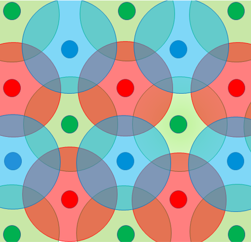
AP cells need to have some overlap to facilitate roaming, but any overlapping cells should preferably be on different channels.This ensures that an AP cell using a particular channel does not have to share, or contend, for that channel with another cell, so that we can maximise the capacity of all the cells. Channels have a limited capacity (explained in Client Device and Wi-Fi Performance), and Wi-Fi devices have to share this capacity half-duplex (meaning they have to take it in turns each time they need to transmit or receive data). Since the signal from an AP only needs to be strong enough for a client device within its cell to receive it clearly, the AP power can be tuned down to fit the required cell size and this also optimises signal quality by eliminating or minimising contention with other cells on the same channel. In the diagram above AP positions, channels and cell sizes are chosen so that no two APs on the same channel overlap.
The diagram above is of course a simplification and that is why a good understanding of the Wi-Fi network is required and careful measurements need to be taken. In the real world, AP cells are unlikely to form regular geometric tesselations and we also have to set up AP cell overlap according to different ranges. I call these ranges the primary operational range, the secondary roaming range and the interference range.
The primary operational range is the range at which the design has been chosen for client devices to achieve the required performance. For many devices the AP cell needs to deliver -65dBm signal strength or better.
The secondary roaming range is the range at which client devices begin to roam and complete their roams. Devices will probe APs at -70dBm or lower, but the roam itself may not take place until a secondary threshold is reached. This may be -67dBm.
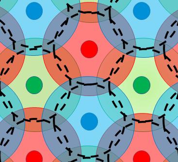
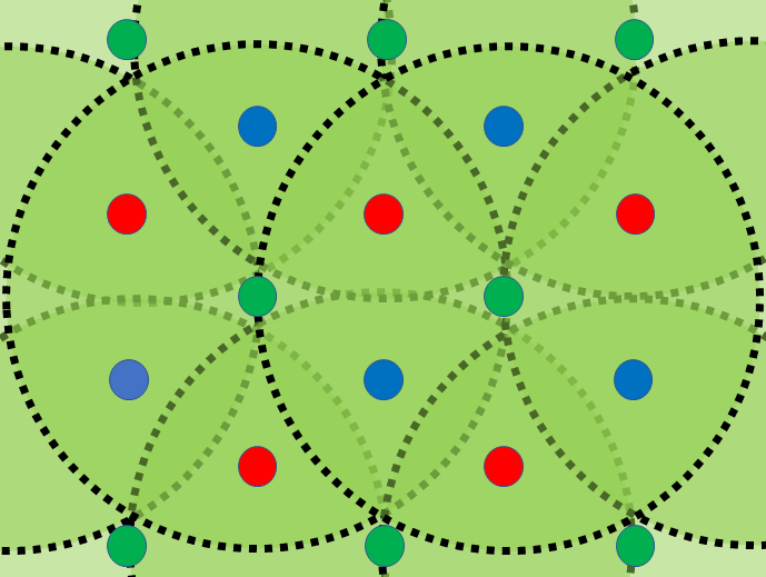
This is represented on the diagram below. Each large circle represents a cell on a particular (colour-coded) channel with its AP in the centre. The area from the outside of each circle inwards as far as the dashed circle would represent the secondary roaming range, and the area from the dashed circle to the AP in the centre would represent the primary operating range.
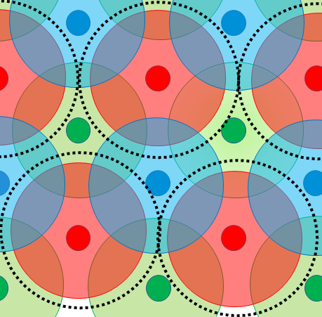
The interference range is the level at which signals extend out at weaker levels from the AP beyond their useful range. This is defined in individual Wi-Fi standards (e.g. Wi-Fi 6 or Wi-Fi 6). It extends out to about -86dBm. The diagram below shows the extent of interference from each red cell/channel, represented by dotted lines. This is just for illustrative purposes. In reality this could extend out much further because dBm is on a logarithmic scale.
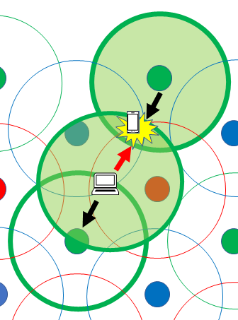
Wi-Fi is designed to handle contention. When two cells on the same channel overlap, so that a client device in the first cell can hear the AP in the second cell at -86dBm or more, and vice-versa, then even if the client device in the first cell cannot receive flow-control messages from the AP in the second cell, then it will at least be able to perform a Clear Channel Assessment to prevent its transmissions interfering with those of other devices (collisions). But, if the client device in the first cell cannot hear the AP in the second cell then its transmissions could interfere with transmissions from the AP in the second cell to its client devices.
In the example below, a laptop operating with its AP in the first cell, interferes with transmissions from the AP in the second cell to a smart phone in the second cell. (This is a variant of something called the hidden node problem because the transmitting device cannot hear the second AP). The diagram only demonstrates how this can happen, in practise the laptop should have roamed nearer the AP in its primary operational range, and the AP and client device transmission patterns and sizes will vary depending on the design criteria.
For this reason the primary operational range of cells in the design should not just account for the interference range of APs, but includes an extra allowance for the interference range of client devices.
So now you can see how turning up AP power, just causes lots of contention and interference within the Wi-Fi network,and this impacts performance. To see for yourself, the following diagram shows what the contention/interference would be like if a network was deployed with lots of power on the green channel.
For this reason cell design should not just account for the interference range of APs, but includes an extra allowance for the interference range of client devices.
To account for, and measure, the big range of interference to the -86dBm level, requires surveying across large floor areas and between floors. That is why we use multiple APs and tripods during the design process to make the survey more practical. Furthermore, it is the roaming behaviour of clients which determine where client devices are effected by and cause interference, and multiple APs and tripods allow us to test for roaming as well.