The way that radio waves are used to transmit Wi-Fi signals and the way they are decoded, make them change from moment to moment.
Individual AP (and client device) antennas generally linearly polarise a Wi-Fi signal, so that the signal is stronger on a certain plane. The type of polarisation will depend on the device.
A client will receive a stronger signal from an AP when the antennas are oriented with the same polarisation (e.g. on the vertical plane) than when the antennas are oriented with a different polarisation (e.g. on a horizontal plane).
APs are generally designed to be mounted horizontally in the centre of a ceiling, as you would place a light fitting, and the shape of the overall antenna coverage pattern and the polarisation of the antennas takes this into account. However, APs with multiple antenna elements are able to transmit and receive signals with different polarisations, to best match the orientation of the client device.
Radio waves are also subject to other effects, such as absorption (which happens when the radio waves travel through walls, ceilings and even people) and that reduces the strength of signals, depending on which path that they follow.
Objects can also diffract, or bend radio waves, so that they fan-in or fan-out on a different path, which again may affect the total amount of absorption they receive and the strength of the received signal.
Importantly, buildings, contents and people all reflect, and scatter radio waves. Reflected signals not only follow different paths, which may effect their received signal strength, but reflected radio waves also change their polarisation which also affects the strength of the received signal. (It is also the reason why polarisation filters used by photographers prevent glare from reflected surfaces, because radio works similarly to light).
Finally, when different waves come together at different points in space, they either add up to create a peak, or cancel each other out to create a trough, which also affects the strength of the received signal.
Since radio waves continually take different paths, so these effects will change over time.
Because a Wi-Fi design relies on the correct tuning of the Wi-Fi parameters, we try to estimate and test these effects during a Wi-Fi survey so that we can find the optimum placement and configuration for APs. But, as there are no absolutes in Wi-Fi, this means we have to allow some tolerance in the parameters so that any practical variances will not break the Wi-Fi design. (Some design software also include a 'button' to add a predetermined offset to the survey results, although in our experience it is better to do this from observations.)
We took some example observations to demonstrate the effects. We checked the signal received from a smartphone that was continuously transmitting, at a small range of distances, and at different orientations, because these would both effect the received signal.
We numbered each of the phone positions we tested 1-6 as follows:
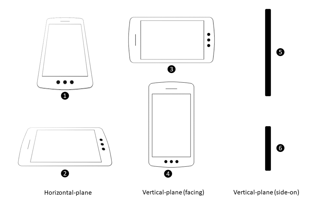
We tested 10,000 frames in each position (1-6), and we ran the tests 4 times from slightly different distances (each represented as a different series).
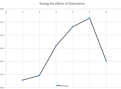
We plotted the average signal strength at each position (1-6) for each distance (series).
In positions 1, 3 and 6 there was a small spread of results, but in positions 2, 4 and 5 there were some tight clusters in the results.
This was all with the exception of series 2, which at this particular distance showed little variance in any position!

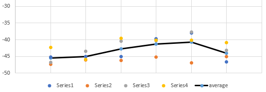
Overall, there was a variance of about 5dB across the range of results, so this would gives an indication of the tolerance required, for this example.