Users' Wi-Fi client devices (Smart Phones, Laptops etc.) are the lowest common denominator in the overall performance of a Wi-Fi network.
We did some sample experiments to show that, despite the specifications of the APs and the specifications of the user's client devices, client performance might not be as good as you expect it to be. Wi-Fi elements that boost performance, such as channel widths are limited by the density of the Wi-Fi network, and as we shall see, that spatial streams are limited by not only the specification but also the behaviour of devices themselves. APs then mitigate for client performance, by further slowing down the slowest devices to limit the airtime they use (airtime fairness), and transmit to multiple clients simultaneously using Multi-User (MU) MIMO if circumstances allow, but of course this is only in the outward direction.
You therefore need to understand this behaviour to understand your client devices, get the overall AP placement and configuration right to get the best performance from your Wi-Fi network, and to be able to meet required capacity.
In this example, we look at a basic Smart Phone (802.11n/Wi-Fi 4, 2.4GHz only, with 1 Spatial Stream) and a Laptop (802.11ac/Wi-Fi 5, Dual Band, with 2 Spatial Streams), they are on the edge of an AP cell, in this case the other side of a wall, where a small AP serves two rooms. For comparison, we also test the effects of adding an external Wi-Fi adaptor to the laptop.

Observations
These are the results we observed:

We see a reasonably good performance from the phone, despite its limited specification, however the AP fails to utilise its capacity.
We see a relatively poor transmit performance from the laptop, despite its better specification, but the AP is able to make reasonable use of its capacity.
When we add an external Wi-Fi adaptor to the laptop, we see significant improvements in performance.
An explanation of the meaning behind these observations follows. But note that the rates reported above are for Wi-Fi data messages (frames) only. As a rule of thumb, only 50% of this translates to an actual user data rate.
1) The data rates that we see are only the data rates used for data frames. Other frames are required for management and control, and these are deliberately sent out at lower rates to ensure reliability in the Wi-Fi network. To run faster, AP placement has to be surveyed to allow the configuration to be changed.
2) Due to corruption in the transmission of messages and messages colliding, 802.11n/Wi-Fi 4 and 802.11ac/Wi-Fi 5 are only about 60% efficient.
3) These rates only account for the physical and data-link levels of communication. Other components used for delivering a network service, a particular grade of end-to-end service, or application-specific services, such as session control (e.g. SCP) or data representation (e.g. HTTP) will add more and more levels of control protocol overhead.
Further application-specific throughput testing can be done, to confirm the expected throughput for deployed applications, using specific applications, client devices and APs.
Components of Data Rate
To understand the performance of client devices, we need to understand the components that make up their data rate.
We will consider these three components of data rate here:
- Modulation and Coding Scheme
- Channel Width
- Spatial Streams
We will provide a brief explanation of each and show how they all fit together.
Modulation and Coding Scheme - Specific frequencies within the overall channel width are each used to encode one of a set of numbers. The phase of each frequency can be shifted, and the amplitude of each frequency can be changed, so that particular combinations of phase and amplitude can be used to represent these different numbers. This is called Quadrature Amplitude Modulation (QAM). In fact our logo is a stylised (i.e. not accurate) representation of three waves on different frequencies (represented as different colours), each with different phase and amplitude patterns. In this example, each wave would represent a different binary number.
![]()
The set of numbers that can be represented at each frequency depends on the particular type of modulation being used. Different modulations can even be used during the course of a connection, to achieve the fastest available data transfer
Some example modulations are 16-QAM which can represent 16 different 'symbols', (equivalent to 4 binary digits or bits - √16), 64-QAM (64 symbols, equivalent to 8 bits), 256-QAM (256 symbols, equivalent to 16 bits) and 1024-QAM (1024 symbols, equivalent to 32 bits).
As the number of symbols increase, so do the nuances between the patterns used to represent them, and hence a greater accuracy of transmission is required to differentiate between them. If the transmission medium is not accurate enough then there will be errors in the transmission. Errors are detected by calculating an error check code from the received data, and comparing that code with the same code generated and sent by the transmitter. In practice, if errors are detected, then rates will reduce until data is transferred reliably.
The symbols are also represented in a way to detect and repair any corrupt bits. The coding scheme is described by a ratio, x/y. Meaning that for every y bits encoded, there are actually x data bits.
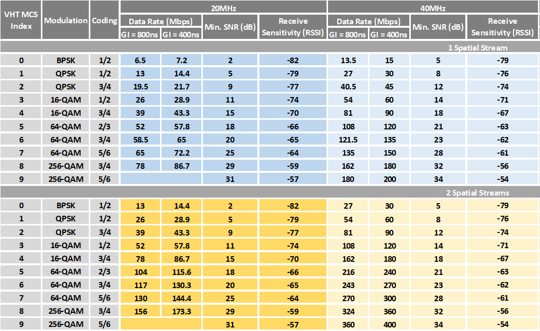
The modulation and the coding scheme together, then determine the data rate. The following table, adapted from one originally produced by Andrew von Nagy, shows the factors that affect the data rate. The Modulation and Coding Schemes (MCS) are shown in the table.

Reflections of the original signal (known as multipath) cause delayed echoes of the original signal to be received, which could potentially corrupt the received symbol. To overcome this, a delay is introduced after the transmission of each symbol, to cover this echo period before the next signal is received, which is known as a Guard Interval. The 802.11 standard defines an 400ns Guard Interval (GI). When there is particularly bad multipath the standard also defines an 800ns Guard Interval (GI). These are known as the Short and Long Guard Interval respectively. The Short Guard Interval is usually sufficient in most cases. The longer the interval, the greater the impact on the overall data rate.
Note that there are also an additional two columns that refer to (a) the signal quality measured as a Signal strength to Noise Ratio (SNR) expressed in dB, and (b) the Received Signal Strength (RSS). We will later see that because our examples are taken at the edge of the cell, when these quality measures fluctuate and fall below the required minimums at these data rates, then the data may get corrupted.
Channel Width - The basic channel width is 20MHz, but on the 5GHz band there is enough room to operate wider channels. We could for example operate a 40MHz-wide channel and effectively double the data rate, because we are using just over double the number of data sub-carriers.
The later standards allow wider channel widths, and some vendors even default to 80MHz-wide channels to make their AP performance look sexy! The problem with wider channels however is that they can generally waste bandwidth, and they do not provide enough independent channels to implement independent cells, forcing contention between APs. There has been both academic and industry research which shows how on 802.11n (Wi-Fi 4) and 802.11ac (Wi-Fi 5) networks, which are the predominant standards for most current client devices, Wi-Fi generally offers better throughput overall with smaller channels. The evidence will be presented in another article, but for now note that despite the channel widths that these standards provide, there are some practical limits to effective channel widths.
We can therefor use up to 40MHz channel widths comfortably to increase data rates.

Spatial Streams - Wi-Fi takes advantage of the fact that it is possible to have separate streams of data on the same frequency. The different streams arise when a device sends out different signals on the same frequency using multiple antennas (with per-antenna radio circuitry). If the receiver also has multiple antennas arranged in the same way, then because of the way that radio waves work, each antenna will receive a different maximum for each of the streams. The per-antenna radio circuitry is then able to separate out the streams.
They are therefore called spatial streams because they are separated by physical space.
Generally, smart phones support only one spatial stream because the extra radio circuitry would reduce battery life, laptops typically support two spatial streams. The addition of a spatial stream, effectively doubles the data rate again.
Example 1 : Simple Smart Phone -
The Smart Phone works only on the 2.4GHz band, so the channel width is 20MHz. It supports one spatial stream.
The signal strength for the phone is received at about -38dBm near to the phone, and down to about -68dBm near to the AP. The total loss is therefore about 29dB.
The signal strength for the AP is received at about -30dBm near to the AP, and down to about -60dBm near to the phone. The total loss is therefore similar at about 30dB.
Although the signal strength for the phone is observed weaker than the signal strength for the AP in this example, everything works as expected. The devices are generally matched in power for the purposes of this test because there is more antenna gain on the AP than on the phone, so the AP signals are amplified more, but it also means that the antenna also amplifies the weaker signals from the phone in the same way.
As the phone consistently hears the AP at about -60dBm it sends data to the AP at 72.2Mbps. For the majority of the time this works reliably. Only on one occasion, after a change in the RF environment do we see the signal drop at the router to -68dBm. There is some loss, and the data rate from the phone drops temporarily to 39.0Mbps when it again becomes reliable.


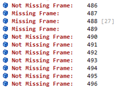
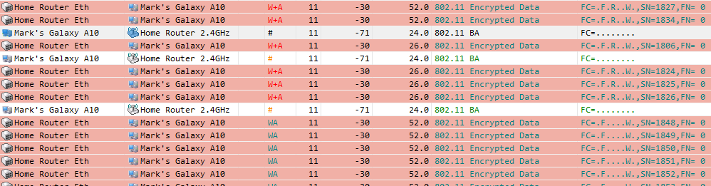
The AP on the other hand hears the phone at about -68dBm, yet it initially tries to send data at 65.0Mbps. This results in some missing frames and a few retransmissions, before the rate settles down to a steady, 52.0Mbps, occasionally dropping to 26.0Mbps.
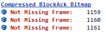
Data retransmitted a second time:
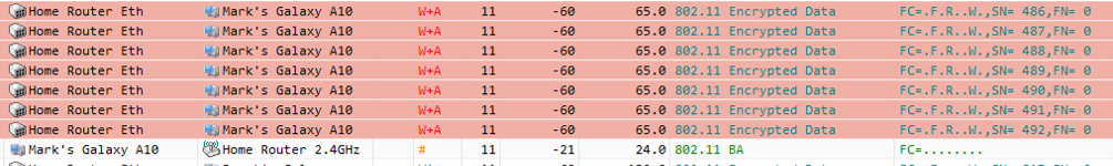
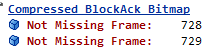
Block Ack showing some further retransmissions are necessary:
Example running at 52.0Mbps, with occasional drops to 26.0Mbps when retransmissions are required.
Example 2 : Laptop -
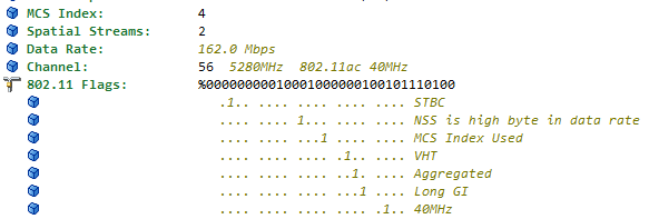
The laptop implements 802.11ac (Wi-Fi 5) on the 5GHz band, and supports two spatial streams. The band is configured for 40MHz channels.
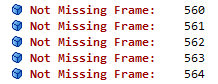
The AP reliably sends data at 162.0 Mbps over a 40MHz-wide channel, using two spatial streams, and occasionally reliably sends data at 216.0 Mbps.
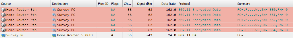
As shown by Block Acknowledgements
The laptop receives a signal strength of -62dBm from the AP, but despite this the laptop only sends data back at 90Mbps, and occasionally drops to 45Mbps or 30Mbps.
We confirm that this is being sent over a 40MHz-wide channel, using two spatial streams.


Example 3 : Laptop with External Wi-Fi Adaptor -
An external Wi-Fi adaptor makes a significant difference to Wi-Fi performance.
In the same environment, our tests showed that there was a sustainable data rate in both directions of 270.0Mbps with bursts of 324.0Mbps.


Conclusion
Careful checks need to be done to understand how your client devices and APs work together, to ensure that AP placement and configuration are right to ensure correct performance and for overall capacity to be managed. If this is done properly, the management and control of the Wi-Fi can also be configured to run faster.